Motor Setup & CAN IDs
Every device gets its own CAN ID, and then the mechanism turns under power for the first time. You prove which way it moves under a volt or two, and on the arm which way its encoder counts first. Get any of that wrong and the next lesson tunes against the wrong sign.
- The mechanism assembled and powered.
- Phoenix Tuner X connected to the CANivore over USB, firmware current.
- No robot program running. Tuner X owns the bus here.
What mechanism are you working on?
The lesson below is written for the one you pick. Switch back any time to read it for the other.
Assign every CAN ID
Factory default each device before you number it. That clears whatever last season left behind. It also resets the CAN ID and the inversions.
Then blink. The device that flashes is the one you are about to edit. If two flash together they share an ID: take one off the bus, number the other, then reconnect.
| Device | CAN ID | Device label |
|---|---|---|
| Arm TalonFX | 31 | Arm motor |
| Arm CANcoder | 32 | Arm encoder |
| Flywheel TalonFX | 21 | Flywheel motor |

- Open a device, click the three dots, then Factory Default.
- Click the Blink button on the left panel. This will flash the lights on the device that you have selected.
- Give it the ID from the table and a name that says which mechanism it drives.
- Repeat until every device has its own ID and Tuner X reports no duplicates.
Arm encoder direction and zero
The encoder is what everything downstream trusts. Test it by hand before any request is sent.
- Open the CANcoder device in Tuner X and plot the position.
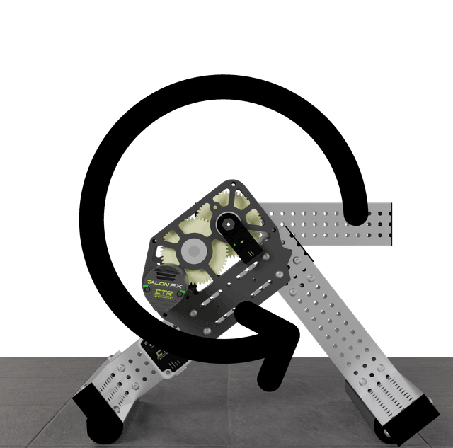
- Facing the motor side of the arm, turn it counterclockwise by hand.
- The CANcoder position must increase. If it decreases, flip the sensor direction, apply, and repeat the hand test.
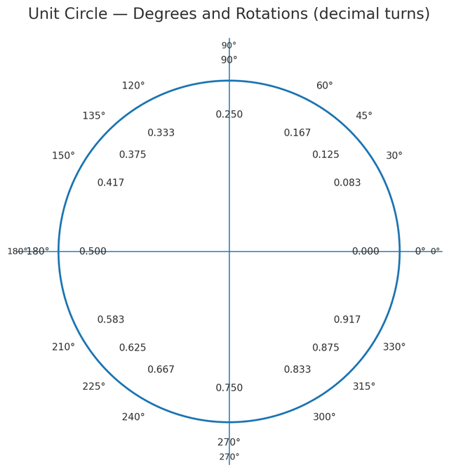
- Put the arm to 0, based on the Unit Circle, then zero the CANcoder position.
- Turn it 90 degrees counterclockwise. Expect about
0.25rotations. A full turn reads1.0.
Positions are measured in rotations, not degrees. One full turn is 1.0. Counterclockwise with the device facing you is positive, and every position target from here to Motion Magic is written that way.


Choose the reference with whoever built the arm, then mark it on the metal. A replaced CANcoder comes back with no direction and no offset, so somebody will run this procedure again in March.
Link the Encoder
Now that you have verified the encoder direction and zero, you can link it to the motor.
- Select the arm TalonFX and scroll down in the config section to the Feedback section.
- Set the
Feedback Remote Sensor IDto match your CANcoder ID. - Set the
Feedback Sensor SourcetoRemoteCANcoder

Run the motor, check the direction
This is the first time anything moves under power. Voltage Out sends a fixed voltage and nothing else: no target, no soft limits, no stopping at the end of travel.
The hand test settled which way is positive. The motor has to agree with the CANcoder, and the motor is the only thing allowed to change from here.
A flywheel has no sensor to agree with, so nothing on the bench decides which way positive goes. You decide, and then the motor has to match. The rule on this robot is that positive runs a game piece the way it is meant to travel, so on the shooter positive shoots. Seen from the motor side, that is clockwise. The motor is the only thing allowed to change from here.
Before you enable anything
Make sure the mechanism is clear of obstacles. Blink the device first: voltage goes to a CAN ID, not to the one you meant. Start at 1 volt and enable for about a second at a time. A Voltage Out request runs until you stop it, into the hard stop if that is where the mechanism is pointed.
- Select the arm TalonFX on
31flywheel TalonFX on21and set the control drop-down to Voltage Out. - Enter
1 V, click DISABLED to enable the device, then disable after about a second. Watch the mechanism, not the screen. - The arm should move counterclockwise and CANcoder
32should count up. - The wheel should spin the way it shoots, which is clockwise seen from the motor side.
- If it moves the other way, invert the motor output, apply, and run the same test again.
Once 1 V is right, repeat at 3 V. Only the speed should change. An arm that will not budge at 1 V is usually fighting friction or gravity rather than bad wiring. Climb in single volts until it creeps, then stop. A wheel takes a moment to come up and coasts for a while after you disable, so give it time before you call the direction. You are checking which way it goes, not how fast.
Check your work
Power the bench down, bring it back up, and walk these checks in order.
You should see
- Blinking any ID flashes the device you expected.
- A volt or two moves the mechanism, and disabling stops it.
- Tuner X lists all devices on your mechanism, each with its own ID and a name.
- The arm reference reads about zero, and a quarter turn reads
0.25. - Turning the arm counterclockwise by hand raises the CANcoder reading, and positive voltage on TalonFX 31 drives it the same way.
- Positive voltage on TalonFX 21 spins the wheel the way it shoots, clockwise from the motor side, and it spins down on its own once you disable.
PID tuning starts on the next page!
Check yourself
You blink one device from the Tuner X list and two devices on the bench flash together. What have you found?
Facing the device side of the arm, you turn it counterclockwise by hand. What should CANcoder do?
What does setting the arm's zero do?
A CANcoder fails in March and somebody fits a new one. What has to happen?
At 1 volt the wheel spins counterclockwise, seen from the motor side. What do you change?
You enable at 1 volt for a second, and the wheel is still turning after you disable. What does that tell you?
Why blink the device before sending it any voltage?